Topology
You will operate an IP network containing some of the largest capital cities in Africa. Your network connects these cities as well as a few selected universities.
Similarly to a real network, your network spans over layer 2 (L2, using switches) and layer 3 (L3, using routers). Your network also connects (at layer 3) to other networks, creating an Internet. We now describe each aspect of the network topology. Focus on getting a general overview. You do not need to remember all the details, and you can always come back to this page later.
L2 Topology
Your network includes two L2 networks, North and South, or L2N and L2S. Within each L2 network, devices are connected via switches. These are connected to the routers of the L3 backbone of your network, which we will discuss in the next section.
As depicted in the figure below, L2N has a single switch S1 (Ashesi University) while L2S has two switches, S2 (University of Cape Town) and S3 (Stellenbosch University).
Switch S1 is connected to the L3 router ACCR and switch S2 is
connected to the L3 router CAPE.
These routers will act as gateways, meaning that a host in, e.g., L2N
must forward a packet to ACCR to reach any non-local destination.
The routers will then take over sending that packet to its destination.

Within each L2 network, host devices are split into two groups:
administrative devices and student devices.
Each switch is connected to one admin and one student host.
Within L2S in the south, hosts should use an IPv4 address in the subnet X.200.0.0/23
and an IPv6 address in the subnet X:200::/32.
In L2N in the north, hosts should only use an IPv6 address in the subnet X:201::/32.
Above and in the following, X is your group number.
L3 Topology
Your backbone network is an autonomous system (AS) and provides transit for neighboring networks.
Your task is to manage this AS.
Your AS number is your group number, e.g., AS 28 for group 28.
The backbone of your L3 network consists of routers located in different African capital cities (Cairo, Khartoum, Addis Ababa, Nairobi, Cape Town, Luanda, Kinshasa, and Accra). There is one router per city, and we use the first four letters of each city as the router name, e.g., CAIR for Cairo, KHAR for Khartoum, etc.

Every AS has been allocated one /8 prefix that it can use internally.
If you are group X, then your prefix is X.0.0.0/8.
E.g., group 48 has the prefix 48.0.0.0/8.
You will use this IP space to allocate IP addresses to your hosts and routers.
Finally, one host is connected to each router (not shown in the figure).
Note: This topology only applies to ASes managed by you and your fellow students. Some ASes are managed by the TA team (see below). These have a smaller internal topology that only contains the router
CAIR.
Internet (AS-level) Topology
Every router except NAIR and KINS has an external connection to one of your neighboring ASes.
Some are connected to a provider, some to a customer, and others to a peer.
ACCR is connected to an Internet eXchange Point (IXP).
During the project, you will establish BGP sessions with your neighbors.
The figure below shows the Mini-Internet topology you will build together with your fellow students, which consists of multiple zones containing several ASes each.
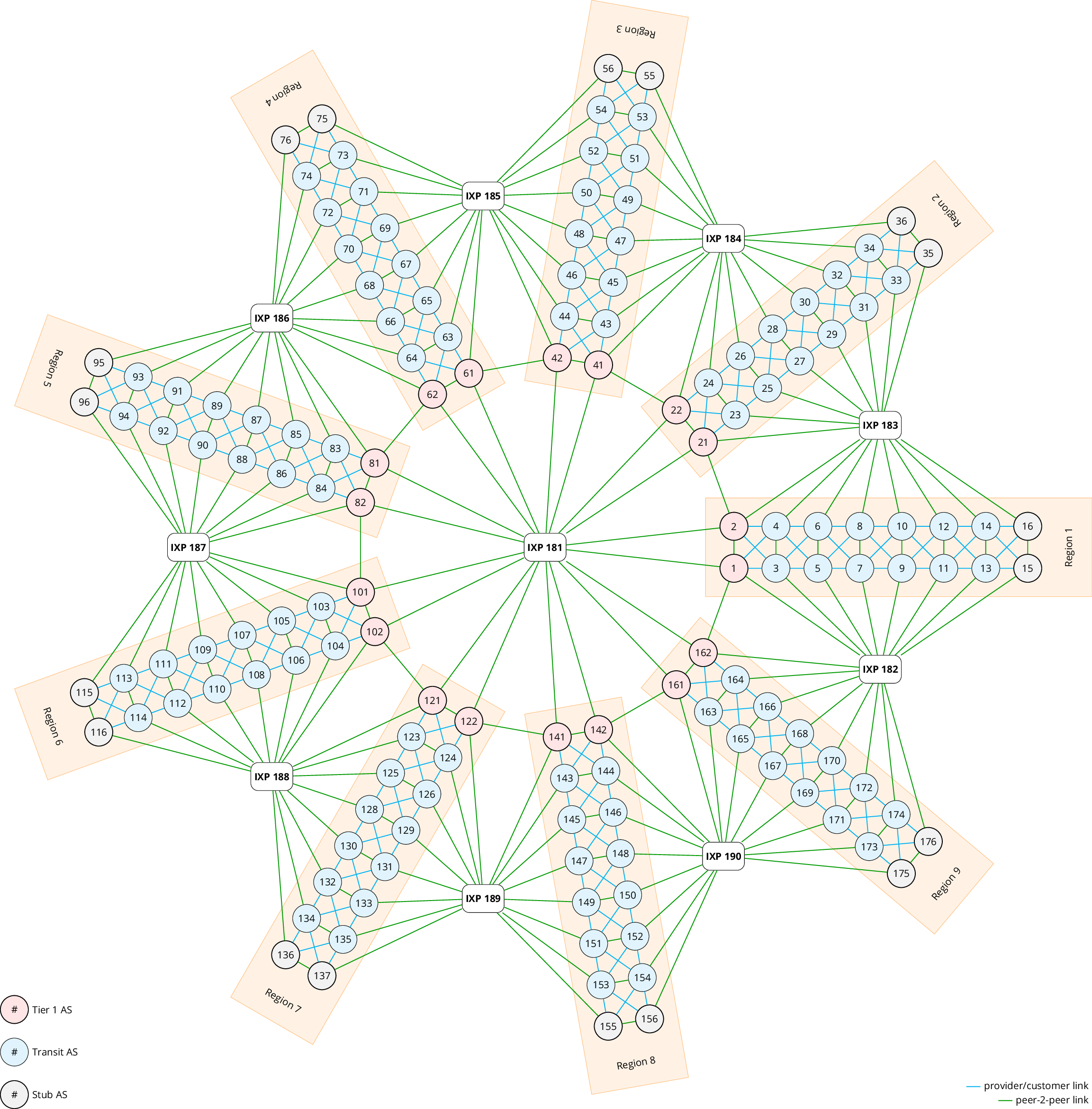
The red ASes (1, 2, etc.) are Tier 1 ASes, meaning their neighboring ASes are either peers or customers, and they have no providers. The grey ASes (11, 12, etc.) are stub ASes, meaning their neighboring ASes are either peers or providers, and they have no customers.
Transit ASes (Tier 2) have peers, customers, and providers. For example, group 5 has two providers (3 and 4), two peers (6 and IXP 141), and two customers (7 and 8).
There are seven IXPs within our mini-Internet. The primary purpose of an IXP is to allow networks to interconnect more easily. One IXP is connected to all Tier 1 ASes, connecting them in a full mesh. The other IXPs always interconnect two adjacent zones. One advantage of using an IXP is that an AS can directly peer with another AS through the IXP instead of reaching it via a provider. This is preferred as you can exchange traffic with a peer for free, while a real-life provider would have to be paid. The following example illustrates the benefit of being connected to an IXP: AS 6 can send traffic to AS25 via the IXP142, instead of paying AS 4 to send the traffic via the path 6-4-2-21-23-25 if IXP142 is not used. Another advantage is that only one physical connection with an IXP is needed to potentially interconnect with all other IXP participants.
We (the TA team) will take care of the Tier1 ASes as well as the stub ASes and several Tier2 ASes. All ASes with a bold border are potentially managed by groups of you and your fellow students, but the TA team may take over some of them depending on the number of groups that have signed up for the project.
Finally, the stub ASes are observed to behave strangely, advertising prefixes via BGP that they should not advertise. You will have to investigate and address this later!
page version 1.0 - last edited May 5th, 2024